Checkpoint error recovery is a procedure (see also go-back-n error recovery) which is implemented in some communications protocols to provide reliability. The operation of checkpoint error recovery is explained in the paragraphs which follow.
During normal operation, a steady flow of PDUs is transmitted by a sending node to the corresponding receiver. This receiver returns information to the transmitter to synchronise the operation of the protocols (for example in the reliable ABM Mode of HDLC to acknowledge the successful reception of a number of I-frames, or to indicate that a receiver is 'not ready' to receive data).
If a receiver fails to receive an acknowledgment for the frames it has transmitted, or when it has sent a frame which requires the remote node to perform a specific action and this action has not been performed, it may commence a process known as "Checkpoint Error Recovery" (known sometimes simply as "polling").
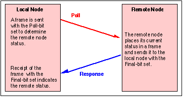
The Checkpoint process plays an important role to ensure the correct operation of a data link protocol. The Checkpoint procedure is triggered when the sender/transmitter detects that it has not received an acknowledgment. It commences with the transmission of a command frame indicating the current state, and with the p/f-bit set to true (see figure).

An Example of Checkpoint Error Recovery: The Poll/Final Exchange in HDLC
When the remote node receives this frame, it replies by transmitting a response frame indicating its current state and also carrying the p/f-bit also set to true. A response with the p/f set to true is known as a "Final" frame. This process, if completed successfully, allows the local node to synchronise its send state information with the remote node's receive state information. (The synchronisation is performed in the direction of transmission of the poll-frame). This allows the transmitter to detect any frames which have not been successfully received and retransmit them.
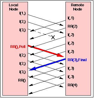
The figure above has been simplified, to show only the two frames involved in the poll. An operational link will normally continue to transfer other frames while the poll is being conducted, and the real picture may look much more complex. The figure below shows an example of this more complex situation. The local node sends a sequence of I-frames, numbered 1,2,3. After a period of time, the sender notes (perhaps through because the T1 timer expires) that no acknowledgment has been received for the I-frame numbered 3. It then performs Checkpoint error recovery by sending a command frame (RR) with the p/f bit set to true (i.e. a poll).

An HDLC Link using Polling to Perform Checkpoint Error Recovery
The receiver receives this frame and notes that the p/f bit was set to true. It therefore generates a response frame (RR) with the p/f bit also set to true. The frame returned by the remote node contains the required information (i.e. the receive sequence number is 3). This confirms that the first two I-frames have been correctly received, the node is willing to receive further I-frames (i.e. the receiver is ready (RR)) and is expecting frame 3. The transmitter is aware that it has already sent a third frame, therefore this information implies implies the loss of the third I-frame (i.e. I(3,), which is therefore resent. This completes the Checkpoint error recovery procedure. The receiver later acknowledges receipt of I(3) by sending a frame with a receive sequence number of 4 (i.e. indicating that it is now expecting to receive frame 4).
The Checkpoint procedure is not affected by any frames sent by the remote node which do not have the p/f bit set to true.
See also: