The Ethernet network may be used to provide shared access by a group of attached nodes to the physical medium which connects the nodes. These nodes are said to form a Collision Domain. All frames sent on the medium are physically received by all receivers, however the Medium Access Control (MAC) header contains a MAC destination address which ensure only the specified destination actually forwards the received frame (the other computers all discard the frames which are not addressed to them).
Consider a LAN with four computers each with a Network Interface Card (NIC) connected by a common Ethernet cable:

One computer (Blue) uses a NIC to send a frame to the shared medium, which has a destination address corresponding to the source address of the NIC in the red computer.

The cable propagates the signal in both directions, so that the signal (eventually) reaches the NICs in all four of the computers. Termination resistors at the ends of the cable absorb the frame energy, preventing reflection of the signal back along the cable.

All the NICs receive the frame and each examines it to check its length and checksum. The header destination MAC address is next examined, to see if the frame should be accepted, and forwarded to the network-layer software in the computer.

Only the NIC in the red computer recognises the frame destination address as valid, and therefore this NIC alone forwards the contents of the frame to the network layer. The NICs in the other computers discard the unwanted frame.
The shared cable allows any NIC to send whenever it wishes, but if two NICs happen to transmit at the same time, a collision will occur, resulting in the data being corrupted.
To control which NICs are allowed to transmit at any given time, a protocol is required. The simplest protocol is known as ALOHA (this is actually an Hawaiian word, meaning "hello"). ALOHA allows any NIC to transmit at any time, but states that each NIC must add a checksum/CRC at the end of its transmission to allow the receiver(s) to identify whether the frame was correctly received.
ALOHA is therefore a best effort service, and does not guarantee that the frame of data will actually reach the remote recipient without corruption. It therefore relies on retransmission protocols to resend any data which is corrupted.
An ALOHA network only works well when the medium has a low utilisation, since this leads to a low probability of the transmission colliding with that of another computer, and hence a reasonable chance that the data is not corrupted.
Slotted ALOHA was introduced to reduce the probability of collissions - but relies on central timing of all senders. This might be possible in networks were there is a master controller in charge of the medium, but is not possible with the decentralised approach used in Ethernet.
The Carrier Sense circuit in an Ethernet transceiver is used to detect the presence of a signal on the media prior to transmission using CSMA/CD. The individual bits are sent by encoding them using Manchester encoding. The presence of another sender using the medium may be sensed by monitoring whether a current is flowing in the cable (each bit corresponds to 18-20 milliAmps (mA)). .
Ethernet uses a refinement of ALOHA, known as Carrier Sense Multiple Access (CSMA), which improves performance when there is a higher medium utilisation. When a NIC has data to transmit, the NIC first listens to the cable (using a transceiver) to see if a carrier (signal) is being transmitted by another node. Data is only sent when no carrier is observed (i.e., no current present at the CS circuit) and the physical medium is therefore idle. Any NIC which does not need to transmit, listens to see if other NICs have started to transmit information to it.
However, CSMA alone is unable to prevent two NICs transmitting at the same time. If two NICs simultaneously try transmit, then both could see an idle physical medium (i.e. neither will see the other's carrier signal), and both will conclude that no other NIC is currently using the medium. In this case, both will then decide to transmit and a collision will occur. The collision will result in the corruption of the frame being sent, which will subsequently be discarded by the receiver since a corrupted Ethernet frame will (with a very high probability) not have a valid 32-bit MAC CRC at the end.
The CS circuit can be also monitored for the remainder of the frame, and is also usually used to provide the CD function to detect when a collision occurs and that triggers back-off and retransmission.
When there is data waiting to be sent, each transmitting NIC also monitors its own transmission. If a sender observes a collision using the CD function (excess current above what it is generating, i.e. > 24 mA for coaxial Ethernet), it stops transmission immediately and instead transmits a 32-bit jam sequence. The set of bytes in the JAM form one part of the minimum frame size needed to ensure correct operation of CSMA/CD. This sequence will ensure that any other node which may currently be receiving this frame will receive the jam signal in place of the correct 32-bit MAC CRC, this causes the other receivers to discard the corrupted frame due to a CRC error.
To ensure that all NICs start to receive a frame before the transmitting NIC has finished sending it, Ethernet defines a minimum frame size (i.e. no frame may have less than 46 bytes of payload). The minimum frame size is related to the distance which the network spans, the type of media being used and the number of repeaters which the signal may have to pass through to reach the furthest part of the LAN. Together these define a value known as the Ethernet Slot Time, corresponding to 512 bit times at 10 Mbps. The CD function MUST be monitored during this interval.
When two or more transmitting NICs each detect a corruption of their own data (i.e. a collision), each responds in the same way by transmitting the jam sequence. The following sequence depicts a collision:

At time t=0, a frame is sent on the idle medium by NIC A.

A short time later, NIC B also transmits. (In this case, the medium, as observed by the NIC at B happens to be idle too).

After a period, equal to the propagation delay of the network, the NIC at B detects the other transmission from A, and is aware of a collision, but NIC A has not yet observed that NIC B was also transmitting. B continues to transmit, sending the Ethernet Jam sequence (32 bits).

After one complete round trip propagation time (twice the one way propagation delay), both NICs are aware of the collision. B will shortly cease transmission of the Jam Sequence, however A will continue to transmit a complete Jam Sequence. Finally the cable becomes idle.
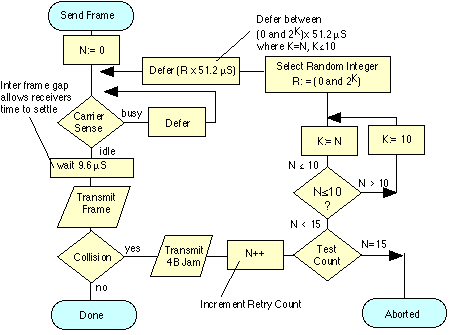
An overview of the transmit procedure is shown below. The transmitter initialises the number of transmissions of the current frame (n) to zero, and starts listening to the cable (using the carrier sense logic (CS) - e.g., by observing the Rx signal at transceiver to see if any bits are being sent). If the cable is not idle, it waits (defers) until the cable is idle. It then waits for a small Inter-Frame Gap (IFG) (e.g., 9.6 microseconds) to allow to time for all receiving nodes to return to prepare themselves for the next transmission.
Transmission then starts with the preamble, followed by the frame data and finally the CRC-32. After this, the transceiver Tx logic is turned off and the transceiver returns to passively monitoring the CD sense for other transmissions at the transceiver .

If all NICs attempted to retransmit immediately following a collision, then this would certainly result in another collision. Therefore a procedure is required to ensure that there is only a low probability of simultaneous retransmission. The scheme adopted by Ethernet uses a random back-off period, where each node selects a random number, multiplies this by the slot time (minimum frame period, 51.2 µS) and waits for this random period before attempting retransmission. The small Inter-Frame Gap (IFG) (e.g., 9.6 microseconds) is also added.
On a busy network, a retransmission may still collide with another retransmission (or possibly new frames being sent for the first time by another NIC). The protocol therefore counts the number of retransmission attempts (using a variable N in the above figure) and attempts to retransmit the same frame up to 15 times.
For each retransmission, the transmitter constructs a set of numbers:
{0, 1, 2, 3, 4, 5, ... L} where L is ([2 to the power (K)]-1) and where K=N; K<= 10;
A random value R is picked from this set, and the transmitter waits (defers) for a period
R x (slot time) i.e. R x 51.2 Micro Seconds
For example, after two collisions, N=2, therefore K=2, and the set is {0, 1, 2, 3} giving a one in four chance of collision. This corresponds to a wait selected from {0, 51.2, 102.4, 153.6} micro seconds.

After 3 collisions, N = 3, and the set is {0, 1, 2, 3, 4, 5, 6, 7}, that is a one in eight chance of collision.
But after 4 collisions, N=4, the set becomes {0, 1, 2, 3, 4, 5, 6, 7, 8, 9, 10, 11, 12, 13, 14, 15}, that is a one in 16 chance of collision.
The scaling is performed by multiplication and is known as exponential back-off. This is what lets CSMA/CD scale to large numbers of NICs - even when collisions may occur. The first ten times, the back-off waiting time for the transmitter suffering collision is scaled to a larger value. The algorithm includes a threshold of 1024. The reasoning is that the more attempts that are required, the more greater the number of NICs which are trying to send at the same time, and therefore the longer the period which needs to be deferred. Since a set of numbers {0,1,...,1023} is a large set of numbers, there is very little advantage from further increasing the set size.
Each transmitter limits the maximum number of retransmissions of a single frame to 16 attempts (N=15). After this number of attempts, the transmitter gives up transmission and discards the frame, logging an error. In practice, a network that is not overloaded should never discard frames in this way.
In a proper functioning Ethernet network, a NIC may experience collision within the first slot time after it starts transmission. This is the reason why an Ethernet NIC monitors the CD signal during this time and use CSMA/CD. A faulty CD circuit, or misbehaving NIC or transceiver may lead to a late collision (i.e. after one slot time). Most Ethernet NICs therefore continue to monitor the CD signal during the entire transmission. If they observe a late collision, they will normally inform the sender of the error condition.
It is simple to calculate the performance of a CSMA/CD network where only one node attempts to transmit at any time. In this case, the NIC may saturate the medium and near 100% utilisation of the link may be achieved, providing almost 10 Mbps of throughput on a 10 Mbps LAN.
However, when two or more NICs attempt to transmit at the same time, the performance of Ethernet is less predictable. The fall in utilisation and throughput occurs because some bandwidth is wasted by collisions and back-off delays. In practice, a busy shared 10 Mbps Ethernet network will typically supply 2-4 Mbps of throughput to the NICs connected to it.
As the level of utilisation of the network increases, particularly if there are many NICs competing to share the bandwidth, an overload condition may occur. In this case, the throughput of Ethernet LANs reduces very considerably, and much of the capacity is wasted by the CSMA/CD algorithm, and very little is available for sending useful data. This is the reason why a shared Ethernet LAN should not connect more than 1024 computers. Many engineers use a threshold of 40% Utilisation to determine if a LAN is overloaded. A LAN with a higher utilisation will observe a high collision rate, and likely a very variable transmission time (due to back off).
A Collision Domain is a set of systems that share access to a cable. This comprises one or more cable segments connected via repeaters and/or hubs. Each switch port constitutes a separate collision domain when CSMA/CD is used on the switch port - typically when it connects to a 10 Mbps LAN. Separating the LAN in to two or more collision domains using bridges or switches would likely provide a significant benefit (assuming appropriate positioning of the bridges or switches).
All broadcast packets must be propagated to all parts of a Broadcast Domain. This is the set of systems that are part of a L3 IP network, although a single broadcast domain may support more than one IP network. A broadcast domain can share a common collision domain, or employ a network that combines several collision domains using bridges/switches as well as repeaters and/or hubs.
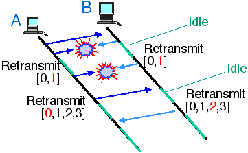
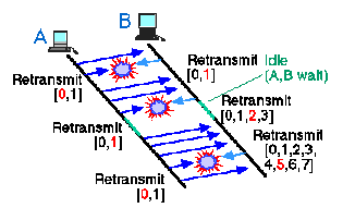
A drawback of sharing a medium using CSMA/CD, is that the sharing is not necessarily fair. When each computer connected to the LAN has little data to send, the network exhibits almost equal access time for each NIC. However, if one NIC starts sending an excessive number of frames, it may dominate the LAN. Such conditions may occur, for instance, when one NIC in a LAN acts as a source of high quality packetised video. The effect is known as "Ethernet Capture".

The figure above illustrates Ethernet Capture. Computer A dominates computer B. Originally both computers have data to transmit. A transmits first. A and B then both simultaneously try to transmit. B picks a larger retransmission interval than A (shown in red) and defers. A sends, then sends again. There is a short pause, and then both A and B attempt to resume transmission. A and B both back-off, however, since B was already in back-off (it failed to retransmit), it chooses from a larger range of back-off times (using the exponential back-off algorithm). A is therefore more likely to succeed, which it does in the example. The next pause in transmission, A and B both attempt to send, however, since this fails in this case, B further increases its back-off and is now unable to fairly compete with A.
Ethernet Capture may also arise when many sources compete with one source which has much more data to send. Under these situations some nodes may be "locked out" of using the medium for a period of time. The use of higher speed transmission (e.g. 100 Mbps) significantly reduces the probability of Capture, and the use full duplex cabling eliminates the effect.
See also
MAC frame header and Ethernet Receive Algorithm
Ethernet Hubs and Repeaters (Collision Domains)
Carrier Sense Multiple Access with Collision Avoidance (CSMA/CA)