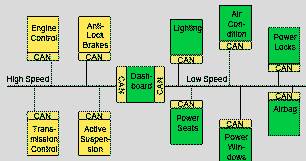
Simplified diagram showing a pair of CAN busses being used to support low and high speed devices.
CAN uses a bi-directional control system designed to operate using three wires: two signal wires, the CANH and CANL wires, and a common ground. If the cable is shielded, the shield is only grounded at one end of the bus. In some applications, a fourth voltage supply wire can be added, for example including a 12V power bus.
The CANH, CANL, and Ground wires are connected to all CAN nodes. The two wires are polarity sensitive so the CANH wire must be connected to the CANH input and the CANL wire must be connected to the CANL input.
While it would be usual to wire the bus sequentially round the nodes, this is not essential. Individual nodes can be connected in a star if this is more convenient.
Like other serial bus designs, a CAN bus requires termination resistors. If the bus is wired sequentially round the modules, then a resistor of 120 ohms should be fitted across the bus at each end. (Smaller buses (or short length) might use just one 60 Ohm resistor between the CANH and CANL wires.)

Simplified diagram showing a pair of CAN busses being used to support low and high speed devices.
The CAN protocol uses Non-Return-to-Zero or NRZ bit coding. This means that the signal is constant for one whole bit time (baud) and only one time segment is needed to represent one bit. The two bus conductors are driven differentially. The signal levels are shifted, resulting in a waveform that differs to that of EIA-485.
The maximum CAN bus speed is 1 MBaud, which can be achieved with a bus length of up to 40 meters using a twisted wire pair. For bus lengths longer than 40 meters, the bus speed must be reduced. A 1000 meter bus can still be realised with a 50 KBaud bus speed. For a bus length above 1000 meters, a design needs to specify the correct speed for the line transceivers .

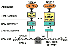
CAN Physical Interface, showing the seprate transceiver chip.
The shifted level results in a special voltage signalling method that is designed to allow bus arbitration. Each low/0 bit is a dominant bit, and each high/1 is a recessive bit. As the name suggests, a dominate bit will take precedence on the bus over a recessive bit when both are sent at the same time by two different nodes.
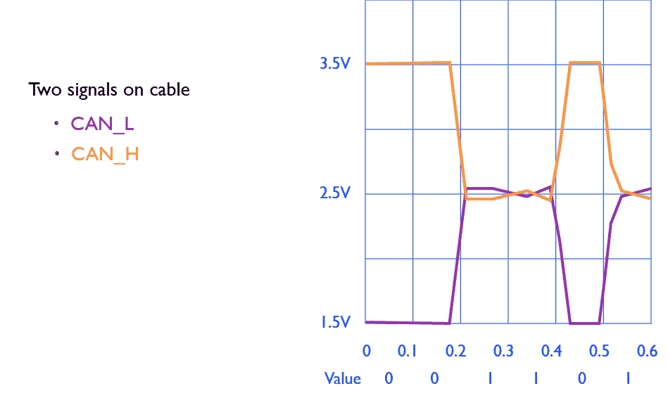
In more detail, CAN singalling represents a 1 and 0 in the following way using 3 signal levels:
This design results in a constant power envelope. That is, the power does not vary depending on the information content, on average the voltage is 2.5V when averaged over many bauds.

Sequence for 1 followed by 0:

Example waveform showing transmission of the sequence { 0 0 1 1 0 1 }. Vertical axis in volts, horizontal axis in microseconds fro a 1 MHz bus.
CAN transmisison is synchornous. Every receiver attempts to reconstruct a phase-aligned clock with the data it receives. This requires a circuit to detect the start of each frame. After detecting the start of the frame, each receiver then synchronises to the frequency and phase of the received bauds to align its local clock to the received data, allowing it to reliably sample around the centre of each baud.
Since bits are delayed by the propagation through the transceiver and along the cable, each receiver will see a clock signal that has a slightly different phase relative to the sender. This is achieved by making small adjustments to the timing of the local receive clock as the receiver observes the time of the transitions at the edge of bits sent in each CAN frame (using a digital phase-locked loop). This process is reset each time at the end of each received frame.
Synchronous transmission is used. That is the sender transmits all bits at the same clock rate. There are no start or stop bauds inserted.
Bit stuffing is used. This stuffing avoids a sender transmitting for excessive period at the same level. This is designed to ensure receiving nodes are able to maintain their clock synchronisation.
When transmitting uisng Bit Stuffing, the sender observes the sequence of bit values being sent. A maximum of five consecutive bits are allowed to have the same polarity. Whenever five consecutive bits of the same polarity have been transmitted, the transmitter will itself adds one bit of the opposite polarity to the previous 5 bits. This is inserted into the bit stream before transmitting further bits. This method can add up to one bit in five, introducing a maximum of 20% additional overhead.
The receiver checks the number of bits received with the same polarity. It removes one bit (the stuff bit) when it sees the previous 5 bits hav the same value. This is called destuffing, and restores the original bit sequence.
Examples of Bit Stuffing:
For example, the sequence 0111111 becomes 01111101 on the wire, but the receiver correctly receives 0111111. Bit stuffing dictates also that the 0111110 becomes 01111100 on the wire, but the receiver then destuff this and receives 0111110, i.e., the receiver will automatically remove any bit after 5 consecutive identical bits.
More examples using Bit Stuffing: a sequence 0111111 becomes 01111101 on the wire, but the receiver correctly receives 0111111 after removing the extra "stuffed" bit.
1010101001 sent on cable, received as 1010101001Figure: Examples of bit stuffing
In correct reception, the removed stuffing bit must always be the opposite polarity to the preceding 5 bits. If the destuffed bit is not of the opposite polarity, then the frame is considered corrupted and is counted as a frame error ("Error Frames" intentionally introduce this error to ensure all CAN nodes see an error).
There is am advantage of being able to send any binary data, while preserving clock transitions. However, this also has a disadavantage when errors result in the unwanted insertion or deletion of bits from the message. While this is likely to be uncommon (there are not usually many stuffing bits - so it is unlikely that they will be corrupted), the receiver must use an integrity check that provides a strong guarantee of detecting destuffing mistakes. In CAN, is acheived using Cyclic Redundancy Check.
Here are some examples of problems that can arise when a stuffed stream is corrupted (i.e. a bit is inverted):
A CAN node does not immediately know if the data it sends will be received (arbitration from a CAN message sent by another node can over-ride the current message with a higher priority message). To detect if the message is actually completely sent, the sender includes an End of Frame (EoF) ths is preceded by an acknowledge (ACK) field this conatines a recessive bit followed by a dominant bit followed by another recessive bit.
A node that correctly receives the EOF confirms reception by setting the (ACK) field to a dominant value. More than one node can make this field dominant with the same result (the ACK field becomes dominant).
Thesending node reads the ACK field of the frame that is sending to the bus: if it detects a dominate bit, this indicates that transmission was successful. If bit remains recessive it indicates transmission was unsuccessful (or no node received the frame), resulting in sending an error frame (and possible retransmission).
The ACK field is essential because it confirms that at least one receiving node on the bus has seen the entire frame sent by a transmitter.
An error frame is sent to informs all other nodes there has been an error, and allow the bus state to be reset the bus. The error frame intentionally adds bit stuffing errors, an illegal sequence that all nodes can easily identify, and results in either an active error frame or a passive error frame.
See also
Prof. Gorry Fairhurst, School of Engineering, University of Aberdeen, Scotland (2025).