Simplified diagram showing main components of a wiring harness before the use of CAN
The CAN bus (Controller Area Network) was developed by the Robert Bosch company in the 1980s for use in motor vehicles. CAN was developed to prevent the need for large multi-core wiring harnesses in the automotive industry. It was triggered by the growing number of electrical/electronic devices including engine management systems, active suspension, ABS, gear control, lighting control, air conditioning, airbags and central locking. This means more safety and more comfort for the driver and of course a reduction of fuel consumption and exhaust emissions. Reduction in complexity and cable weight were important for many applications.
CAN has since been applied to many other types of machinery including aircraft, model control, medical scanners, military vehicles, etc. It became an open international standard for automotive applications as ISO 11519, published in 1994.

Simplified diagram showing main components of a wiring harness before the use of CAN
As in other control busses is a trade off of bus speed against cable length. For example, a bus operating at 125 kbps allows a bus length of up to 500 metres. The signal wire should be a twisted pair and ground, but does not need to be screened. A higher speed version as ISO 11898 in 2003.

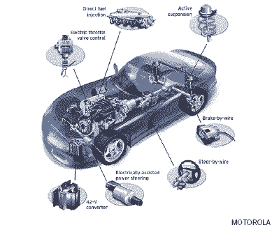
CAN bus subsystems in a car, original figure: Motorola
CAN is most widely used in the automotive and industrial market segments. It defines the Link and the Physical Layer of a control bus. A number of higher level protocols are available for CAN. Typical applications are cars, utility vehicles, and industrial automation. Low cost devices are available due to mass production and have also found applications in trains, medical equipment, building automation, household appliances, stage lighting control, office automation, and a variety of other areas.
A basic system consists of several control units (nodes). Nodes are connected in parallel to the bus via transceivers. This means that the same conditions apply to all nodes. In other words, all the nodes are handled equally, none has any preference. In this context, this is called a multimaster architecture.
Information is exchanged in the form of messages sent serially in frames. Any CAN node can send or receive messages. A message contains values such as the engine speed (rpm). At each receiving node the voltage values are converted back into a bit stream. Each node then converts the values back into messages. For example: the value 00010101 is converted back to the engine speed 1800 rpm.
There are now a wide applications base for CAN and off the shelf components are readily available. It is used for transmission of small amounts of data between devices for control where response times and safety were paramount. CAN is used in virtually all modern motor vehicles, and most cars have multiple CAN busses for different uses.
See also
Prof. Gorry Fairhurst, School of Engineering, University of Aberdeen, Scotland (2025).